Archives de l’auteur : mywikieln

TEMAC

TEMAC

Précédemment GEMAC avec ISE version <=11.
Le GEMAC est disponible au LLR, projet Calice et peut évoluer vers un EMAC 1G uniquement.

Version 4.4, Avril 2010

  • Data Sheet http://www.xilinx.com/support/documentation/ip_documentation/tri_mode_eth_mac_ds297.pdf

et sur le svn [source:/trunk/DOC/TEMAC/tri_mode_eth_mac_ds297.pdf]

  • User’s guide http://www.xilinx.com/support/documentation/ip_documentation/tri_mode_eth_mac_ug138.pdf

et sur le svn [source:/trunk/DOC/TEMAC/tri_mode_eth_mac_ug138.pdf]

LlrLaserHardware

Hardware allocated to the laser room

No modifications to hardware allocated the room are allowed

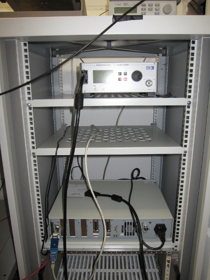
Control rack

Additional Rack

An empty rack is available inside the laser room if you need to add hardware close to the bench.

Wave Generator

[raw-attachment:33220_user_guide.pdf Agilent 33220A User’s Guide]

Scope

A LECROY LT344 is allocated by default. It is possible to use another scope if needed.

[raw-attachment:LT344_Datasheet.pdf LT344 Datasheet]

[raw-attachment:LT344_Manual.pdf LT344 Manual]

Sourcemeter

The Keithley is not always available.

[raw-attachment:Keithley_6485_6487_manual.pdf Keithley 6487 Manual]

Power Supply

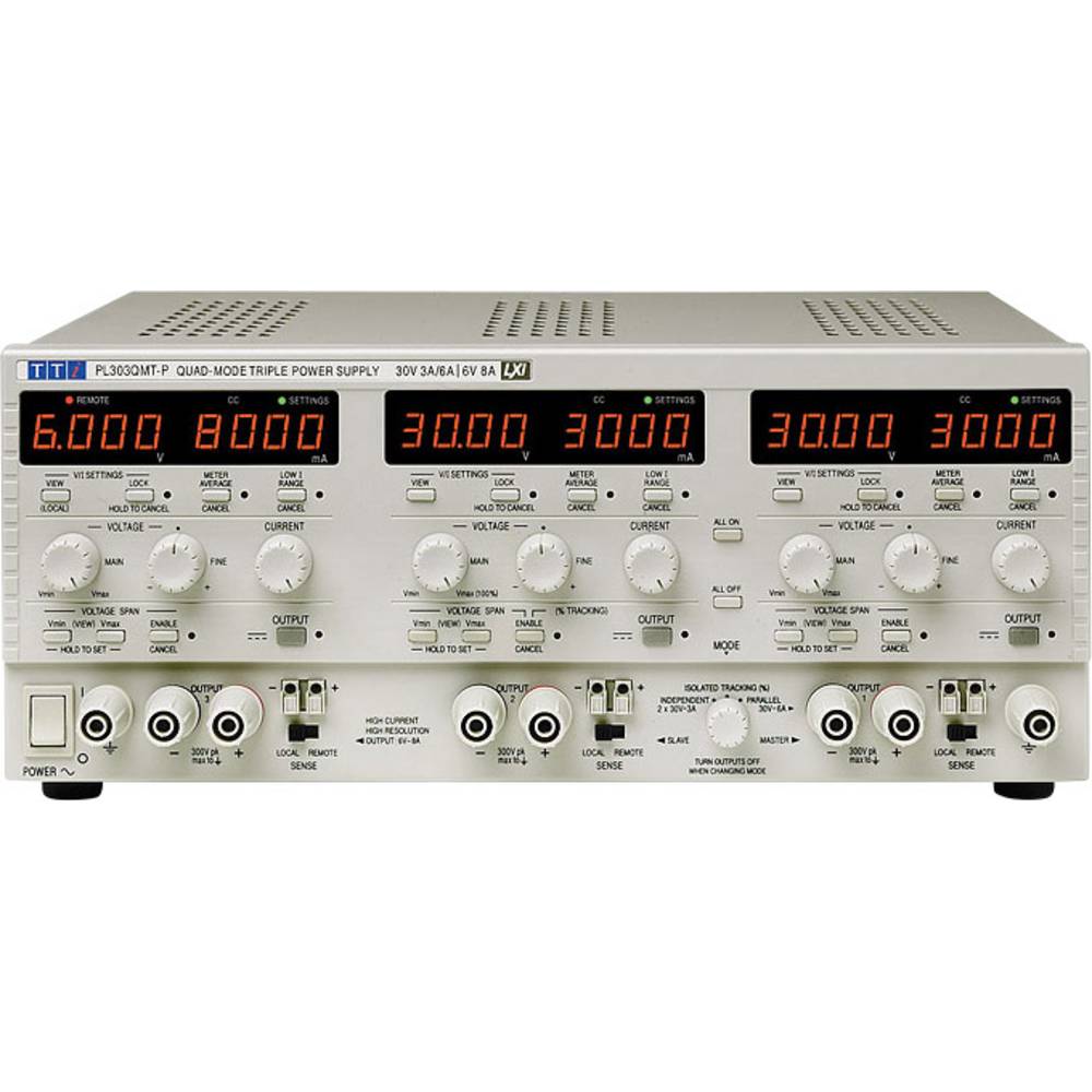
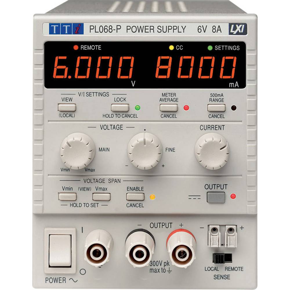
TTI PL303QMT and TTI PL068

[raw-attachment:TTI-PL_Series_manual.pdf TTI PL303QMT&PL068 Manual]

Laser controller

ALS EIG2000DX

[raw-attachment:Manuel_PiLas.pdf PILAS Manual]

Moving stage & controller

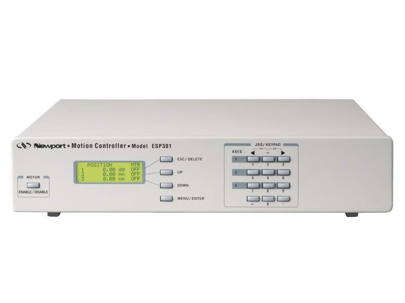
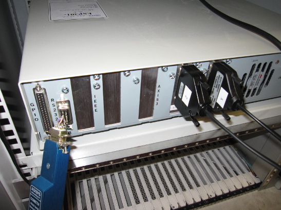
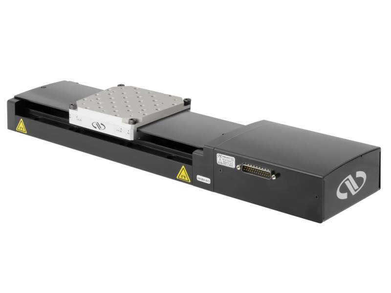
Two Newport ESP301 ([raw-attachment:ESP301_User_manual.PDF Newport ESP301 Manual]) 3 axis controller are available.

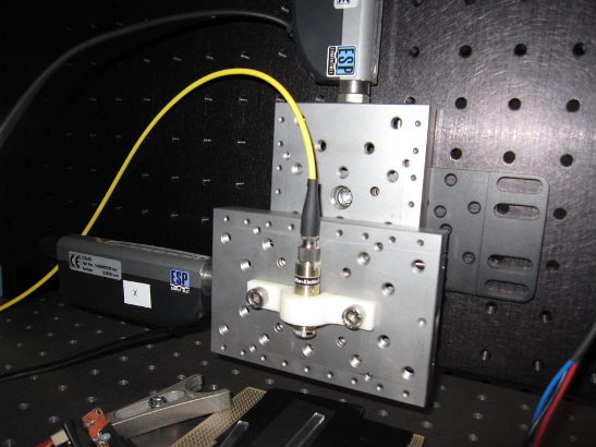
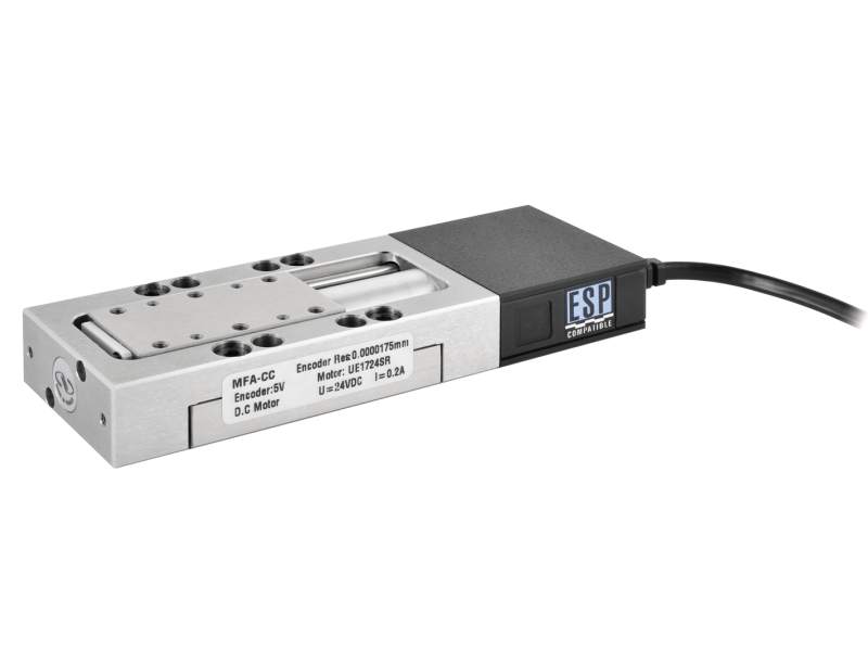
Five motorized moving stages are available:
– 2 Newport LTA-HS: [raw-attachment:LTA-User-s-Manual.pdf LTA-HS pdf manual]
– 1 Newport MFA-CC: [raw-attachment:MFA-User-s-Manual.pdf MFA-CC pdf manual]
– 2 Newport M-ILS200CC: [raw-attachment:ILS-User-s-Manual.pdf M-ILS200CC pdf manual]

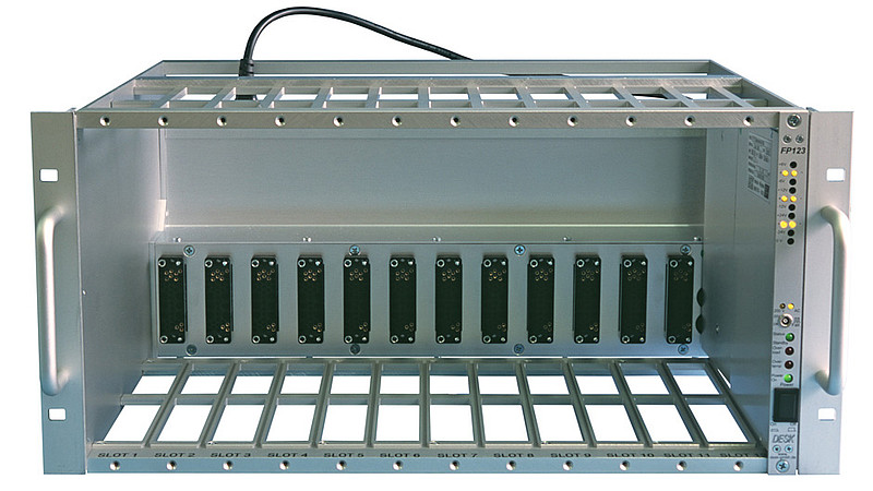
NIM crate

Empty NIM crate.

Interlocks

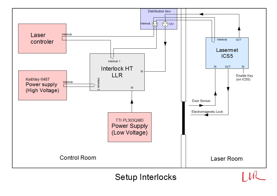
2 Interlocks are available to protect the operator and work together.

– One to lock the access of the room

– The other one is a custom interlock to control the hardware of the room (the High Voltage power supply and the Laser Controller)

More details about interlocks and safety

Cabling

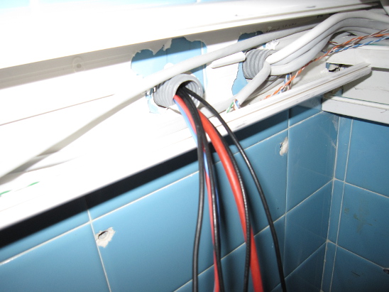
Through wall cabling is limited. Up to now : 4 lemo cables, 1 HV (SHV), 1 low power supply.

Axis control and laser control must unfortunately cross the ajar door.

Light sources

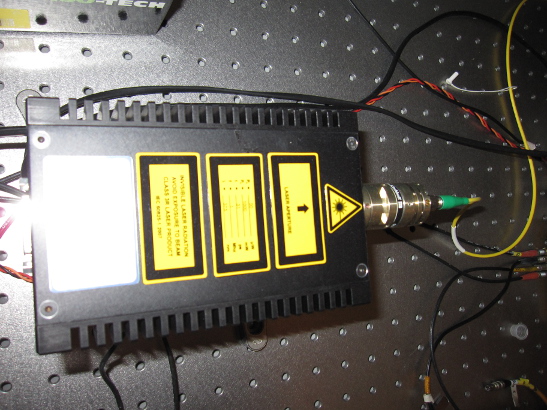
Laser heads

One 373nm (blue) laser head : [raw-attachment:Laser_bleu.pdf] provides 30 ps, 10pJ light pulses.

One 1056nm (IR) laser head : [raw-attachment:Laser_IR.pdf] provides 30 ps, 8pJ light pulses.

LED pulsers

400 nm, RS 713-5043

365 nm (Farnell 231-3512), BFR93 switch : power 2.2 – 2.6V, pulse 0-1.2-1.8V

Laser accessories

Optical power meter

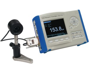
One Newport 1918-R power meter with a 918D Detector included

[raw-attachment:RevA1918-RPowerMeterUsersManual.pdf Newport 1918-R Manual]

[raw-attachment:918D-Manual-RevD.pdf Newport 918D Manual]

Electronic Shutter

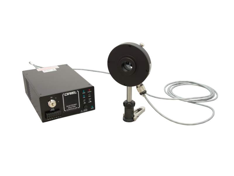
One electronic shutter controller Newport 76995 with the electronic shutter Newport 76994

[raw-attachment:Oriel-76995-User-Manual.pdf Newport shutter Manual]

Computer

llrlaserbench
10.220.0.2
134.158.130.150

login laserbench/laserdaqtest

The control computer is running with linux.

An installation of pyrame [http://llr.in2p3.fr/sites/pyrame] is provided for controlling the moving stages and most of electronics apparatus (oscilloscopes, power supplies…).


Attachments

LlrLaserInterlock

Safety and Interlocks

Laser beam used are invisible 3R Class, it can damage your eyes irreversibly with a direct exposure.

Always wear safety goggles when you go inside the laser room

Global interlock Setup

[raw-attachment:Utilisation_interlock.pdf Interlock Use (French)]

Lasermet ICS-5 interlock

This interlock is used to lock the door between the control room and the laser room.

You need to activate this interlock first inside the room, before using the laser.

[raw-attachment:Lasermet_ICS5_Manual.pdf Lasermet ICS-5 Manual]

[raw-attachment:Lasermet_WarningSign.pdf]

[raw-attachment:Lasermet_KP12.pdf]

Interlock HT (custom)

This interlock is a custom interlock to protect the user from the High-Voltage power supply and the laser radiations from the laser controler.
You can’t activate High voltage and Laser while you are inside the laser room.

The interlock can be remotly controlled on the computer and have a database to save the events that occur.
It is also connected to a signal tower installed outside the room in the main corridor.

[raw-attachment:Manuel_utilisateur_interlockHT.pdf Interlock HT user manual (French)]

Connecteur interlock, embase male 4 pt (6487) : CS-458
http://www.keithley.fr/products/accessories/connadaptools/?mn=CS-458

Câble interlock femelle : 6517-ILC-3


Attachments

WikiStart – Laser

Detector testbench (laser and LED pulser)

Located in room 04 2001.

Acces procedure

1. Discuss your need with the electronics team.
2. Plan appropriate developments (if needed)
3. Book using calendar « SalleLaser »
4. Follow the security training
5. Install hardware/software
6. Use !

Safety and use of the room

Access to the global use of the room

Hardware

Access to the Hardware page

Software

Access to the Software page

LlrLaserSoftware

Software

Use of PC

A PC (linux) is provided (name : llrlaserbench)

Log-in using laserbench user (tip : laserdaqtest).

Switch to superuser typing su -

Software installation

If Pyrame is not installed (i.e. /opt/pyrame does not exist):

1. Download it: [raw-attachment:pyrame_2.0.tgz]

2. Install the dependencies:

yum -y install gcc python python-devel python-pip expat-devel gdbm-devel

3. Move pyrame_2.0.tgz to /root/ and:

cd /root
tar -xvzf pyrame_v2.0.tgz
cd pyrame
make install

If laserbench is not installed (i.e. /root/laserbench does not exist):

1. Download it: [raw-attachment:laserbench_v1.0.tgz]

2. Move laserbench_1.0.tgz to /root and:

tar -xvzf laserbench_1.0.tgz

Calibration of SiPM setup

0. Go to the folder where you want to store your data

1. Adjust the parameters in /root/laserbench/sipm_gain.py to your needs. They are variables initialized at the beginning of the script.

2. Reflect any changes you’ve made in sipm_gain.py in /root/laserbench/sipm_gain.sci

3. If you need a series of calibrations, use /root/laserbench/multiple_calibs.sh

4. In a terminal, launch Pyrame

kill_pyrame.sh; sleep 3s; /root/laserbench/launcher.sh &

5. In another terminal, launch the acquisition script

./root/laserbench/sipm_gain.py

5. In another terminal, launch the analysis script

/opt/scilab/bin/scilab-adv-cli -nb -f /root/laserbench/sipm_gain.sci

Example of profile acquisition of scintillator strip =

0. Go to the folder where you want to store your data

1. Adjust the parameters in /root/laserbench/tile_profile.py to your needs. They are variables initialized at the beginning of the script.

2. In a terminal, launch Pyrame

kill_pyrame.sh; sleep 3s; /root/laserbench/launcher.sh &

3. In another terminal, launch the acquisition script

./root/laserbench/tile_profile.py

Example of stage controller operation

1. In a terminal, launch Pyrame

kill_pyrame.sh; sleep 3s; /root/laserbench/launcher.sh &

2. Go to the module of the motion controller

cd /root/pyrame/motion/cmd_nw_esp301

3. In another terminal, initialize the motion controller

./init.sh "eth/10.220.0.80:2300"

(url of the moving stage controller)
This returns an id.

4. In the same terminal, initialize any axis you need

./init_axis.sh <id from the previous command> #axis position_min position_max

This returns an id_axis of the axis.
Axis are numbered as on the controller : from 1 to 3.
id_axis=axis-1

4. Send the commands you want. For example:

./get_pos.sh <id_axis>

Example :
>kill_pyrame.sh ; sleep 3s; /root/laserbench/launcher.sh &

>cd /root/pyrame/motion/cmd_nw_esp301

>./init.sh « eth/10.220.0.80:2300 »

>./init_axis.sh 0 1 10 50

>./get_pos.sh 0

>./move.sh 0 5 1


Attachments
WikiStart – cosmic

Page regroupant l’ensemble des documents pour le Banc Cosmique du LLR

  • L’eLog du Banc Cosmique a été supprimé faute d’utilisation (il était ici : [http://llroffice.in2p3.fr/elog/cosmic]).
  • Le svn est accessible :
  • Avec un navigateur web : [source:/ Trac] ou ViewVC
  • Avec un client svn (eg. ‘svn’ sous unix, Tortoise sous windows) : https://llrforge.in2p3.fr/svn/cosmic

Pour avoir accès en écriture au svn, au trac ou à l’elog, merci de remplir ce formulaire et nous envoyer le mot de passe chiffré.

Vue d’ensemble du banc cosmique

Le rapport de stage disponible au bas de cette page contient les éléments de la mise en œuvre du banc.

Détails du banc de test nouvelle génération

easicosmic

Détails du banc de test actuel :

Le banc de test actuel est composé d’une partie Trigger (Hodoscope) et d’une partie Acquisition.
Il a servit à diverses expériences, notamment pour acquérir des données de tous types de détecteurs en utilisant le trigger.
Un PC permet de contrôler et d’acquérir l’ensemble des données.

Les matériels

L’hodoscope :

La partie hodoscope est constituée :
– De scintillateurs plastiques montés sur 4 plans X1, X2, Y1 et Y2.
– D’un module haute tension CAEN qui alimente les photomultiplicateurs (PM) collés sur les scintillateurs Réglage des alims ancien setup. Les Alims HT ont été remplacées en janvier 2012.
– D’une carte permettant l’amplification des signaux de détection sortant des PM nommée H4 board.
Les documents concernant la réalisation de cette cartes sont ici, ce .rar contient des documents sur les éléments équipant cette carte ainsi qu’une liste des composants. Pour le routage, il faut s’adresser au groupe électronique du laboratoire ou accéder au disque projet_Cadence sur la machine polcad01 afin d’ouvrir le projet HDA.
– D’une carte avec un CPLD assurant la fonction combinatoire de détection d’un cosmique nommée Hodotrig documentée ici (Conception de la carte Hodoscope).
– D’un chassis au format NIM permettant de retarder les signaux de déclenchements. Le document accessible ici( Réglages du chassis NIM ) permet de configurer les réglages en temps des signaux provenant de la carte Hodoscope pour permettre le déclenchement de la lecture des SLABs du prototype physique ECAL de l’expérience CALICE.

Le PC contrôle et acquière les données de cette carte avec un module d’entrées-sorties numériques (USB-DIO) constitué de 3 ports de 8 bits.
– Remise en route du banc cosmique à l’aide d’une Alimentation CAEN SY527 avec liaison serie RS232 sous hyperterminal Reglage au 18/01/2012.

La partie Acquisition :

La partie Acquisition est spécifique aux tests des Wafers de l’ECAL de CALICE.
Elle est constituée de :
– Une carte de génération des signaux de contrôle d’acquisition VTC.
– Une carte d’acquisition analogique / numérique au format PCI de National Instrument.

Le PC contrôle la carte VTC avec un module d’entrées-sorties numériques (USB-DIO) constitué de 3 ports de 8 bits.

Pour plus d’informations sur les différents éléments :

Dans le cadre du test des PCB, deux fichiers Matlab ont été utilisés :


Attachments